

hey everyone,im resatarting my blast furnace project that i stopped mid consturction for lack of materials.well i've got the things i neeed and i hae a pretty unusual question: what size I beams should i use in the cast house? the floor is concrete so i figure pretty large there,atleast 18in tall and atleast 1ft tall for the roof trusses as its a very large span.if anyone knows of a website for strngth regulations or distance regulations on I-beams and structural materials. it would be very helpful.id even like construction tips on how the peices are joined,etc.TIA.--josh
I-beam size?
- Thread starter bigsteel
- Start date
You are using an out of date browser. It may not display this or other websites correctly.
You should upgrade or use an alternative browser.
You should upgrade or use an alternative browser.
I'm not sure about the sizee of the "I" beams needed, but I would suggest that you use K&S brass "I" beam stock rather than plastic. The brass stock will be a lot closer to scale thickness. The various plastic structural shapes are generally way too thick to be scale sized.
hey everyone,im resatarting my blast furnace project that i stopped mid consturction for lack of materials.well i've got the things i neeed and i hae a pretty unusual question: what size I beams should i use in the cast house? the floor is concrete so i figure pretty large there,atleast 18in tall and atleast 1ft tall for the roof trusses as its a very large span.if anyone knows of a website for strngth regulations or distance regulations on I-beams and structural materials. it would be very helpful.id even like construction tips on how the peices are joined,etc.TIA.--josh
I could give you strength properties...as I have a small library of civil engineering reference books. Typically older buildings were designed to use 16' grid construction...modern buildings use 32'.
The mill that I worked in had "H" columns about 6'x2' (the crossbar of the H is the 6' measurement), but these were the supports for the crane runways. Extensions to support the roof, about 2'x2', sat atop these. Spacing between the columns was probably be about 30' - 35'.
The casthouse floor would be supported by smaller columns than that, though, perhaps 18"x18" or 2'x2'. The outer perimeter ones, which also support the crane runways, would be larger. Don't forget that all of the columns below the casthouse floor should be covered in refractory brick, in case of a breakout or spill.
Wayne
The mill that I worked in had "H" columns about 6'x2' (the crossbar of the H is the 6' measurement), but these were the supports for the crane runways. Extensions to support the roof, about 2'x2', sat atop these. Spacing between the columns was probably be about 30' - 35'.
The casthouse floor would be supported by smaller columns than that, though, perhaps 18"x18" or 2'x2'. The outer perimeter ones, which also support the crane runways, would be larger. Don't forget that all of the columns below the casthouse floor should be covered in refractory brick, in case of a breakout or spill.
Wayne
6' by 2' !?!? thats HUGE,but i guess if its holding up a 250 ton crane then it would need something that big
.so let me get this straight,the cast house floor was supported by 2' by 2' colomns surrounded by refractory brick.and around the outside of those on the perimeter were larger ones that go past that holding up the crane and above THAT there were smaller ones holding up the roof,am i correct here? il post a pic in a minute.--joshUsually, the columns that serve multiple functions are assembled before being installed, so they'll be widest at the bottom if they're supporting a heavy floor, then overhead crane runways, and finally, the roof. The outside face is usually continuous, with the inside face stepped back to provide a bearing surfaces for the various loads. The columns for a blast furnace casthouse probably wouldn't exceed 2'x2', as the cranes there don't carry ladles and the spans of both cranes and roof are not that great.
It's too bad that I threw away the set of blueprints that I had for a blast furnace, as all of the major dimensions would've been readily available.
It just occurred to me that I have a few odds 'n' ends left over from that project: the casthouse floor supports were about 1'6"x1'6" square, while the main columns on the outer sides of the building were no more than 4'x4'. The roof span was only 75', and this was for a large furnace.
The crane shown below started out as one of the two casthouse cranes for my furnace project, but when that died due to lack of both space and funds, I altered it, basing it on three different cranes in the department where I worked at the time. Except for a few repairs carried out when I built this scene, all of the smaller structural shapes on the crane itself are basswood, including the handrail angle irons. Believe me, it's a lot easier cutting styrene columns and shapes than those basswood ones, which split so easily.

Wayne
It's too bad that I threw away the set of blueprints that I had for a blast furnace, as all of the major dimensions would've been readily available.
It just occurred to me that I have a few odds 'n' ends left over from that project: the casthouse floor supports were about 1'6"x1'6" square, while the main columns on the outer sides of the building were no more than 4'x4'. The roof span was only 75', and this was for a large furnace.
The crane shown below started out as one of the two casthouse cranes for my furnace project, but when that died due to lack of both space and funds, I altered it, basing it on three different cranes in the department where I worked at the time. Except for a few repairs carried out when I built this scene, all of the smaller structural shapes on the crane itself are basswood, including the handrail angle irons. Believe me, it's a lot easier cutting styrene columns and shapes than those basswood ones, which split so easily.
Wayne
heres what i have so far,as i dont know how 2 beams are attached to make a truss i left it blank for now,an info on this will also help.the beam going cross ways would be for the crane.also,did anything go cross wise on the cast houoor or was it just steel re-inforced concrete?--josh
Your drawing looks pretty good - in the drawing at right, you can see the crane runway girder sitting atop the step in the roof support column.
The roof trusses are built-up from structural shapes, and might be welded, bolted, or riveted together. The truss shown below is built-up from basswood angles, with styrene gusset plates. The bottom and top chords are 6"x6" angles, back-to-back, with the gusset plates sandwiched between them, while the intermediate members are 4"x4" angle, single pieces only (although I don't recall if they were supposed to be single or if they should've been double, but I just got lazy) The span across the bottom member is 75', and the distance from the bottom to the peak is 27'.


For the casthouse floor, I'm not sure what the spacing of the floor support columns would be, but judging from photos of my model, it looks like 20' to 25', and this would be in a square pattern under the entire floor. These were connected by a grid of I-beams. The floor itself would've been reinforced concrete, with an overlay of hearth refractory brick. Concrete, when molten iron or steel hits it, tends to explode. The slag and iron runners were set into the floor and were also lined with refractory. For my model, the support columns for the crane runways and roof were separate from the floor support columns, so there was a double row of columns around the perimeter. The columns at the ends of the casthouse (beneath the gable ends) were not as large as those supporting the roof and cranes - probably 1'6"x1'6" at most, since they supported only the end wall.
The crane runway is usually composed of heavy I-beams, although longer spans would use a built-up girder similar to a railroad girder bridge, while exceptionally long spans would be a truss, again like a bridge.
Hope this info helps. I never worked in the blast furnace or the open hearth, but I do have some photos, plus the book from U.S.Steel, and of course a vague memory of those blueprints. I see that Dean Freytag's book on modelling the steel industry is now available - about $70.00 at the LHS.
Wayne
The roof trusses are built-up from structural shapes, and might be welded, bolted, or riveted together. The truss shown below is built-up from basswood angles, with styrene gusset plates. The bottom and top chords are 6"x6" angles, back-to-back, with the gusset plates sandwiched between them, while the intermediate members are 4"x4" angle, single pieces only (although I don't recall if they were supposed to be single or if they should've been double, but I just got lazy)
The span across the bottom member is 75', and the distance from the bottom to the peak is 27'.
For the casthouse floor, I'm not sure what the spacing of the floor support columns would be, but judging from photos of my model, it looks like 20' to 25', and this would be in a square pattern under the entire floor. These were connected by a grid of I-beams. The floor itself would've been reinforced concrete, with an overlay of hearth refractory brick. Concrete, when molten iron or steel hits it, tends to explode.
The slag and iron runners were set into the floor and were also lined with refractory. For my model, the support columns for the crane runways and roof were separate from the floor support columns, so there was a double row of columns around the perimeter. The columns at the ends of the casthouse (beneath the gable ends) were not as large as those supporting the roof and cranes - probably 1'6"x1'6" at most, since they supported only the end wall. The crane runway is usually composed of heavy I-beams, although longer spans would use a built-up girder similar to a railroad girder bridge, while exceptionally long spans would be a truss, again like a bridge.
Hope this info helps. I never worked in the blast furnace or the open hearth, but I do have some photos, plus the book from U.S.Steel, and of course a vague memory of those blueprints. I see that Dean Freytag's book on modelling the steel industry is now available - about $70.00 at the LHS.
Wayne
Wayne,
steel constuctions per excellance again! Congratulation!! :thumb: :thumb: :thumb:
Nice to see such fine model constructions which give new ideas and incitation for own models.
Bernhard
steel constuctions per excellance again! Congratulation!! :thumb: :thumb: :thumb:
Nice to see such fine model constructions which give new ideas and incitation for own models.
Bernhard
The roof trusses are built-up from structural shapes, and might be welded, bolted, or riveted together. The truss shown below is built-up from basswood angles, with styrene gusset plates. The bottom and top chords are 6"x6" angles, back-to-back, with the gusset plates sandwiched between them, while the intermediate members are 4"x4" angle, single pieces only (although I don't recall if they were supposed to be single or if they should've been double, but I just got lazy)
OK,that seems simple enough
,i even have the right size angle so i could probably build those tonight or tomorrow :thumb:,since my Bf is only half a structure with a depth of 57ft,ill have to use trusses designed for 114ft .so they'll be a little bit bigger than your truss pictured .For the casthouse floor, I'm not sure what the spacing of the floor support columns would be, but judging from photos of my model, it looks like 20' to 25', and this would be in a square pattern under the entire floor. These were connected by a grid of I-beams. The floor itself would've been reinforced concrete, with an overlay of hearth refractory brick. Concrete, when molten iron or steel hits it, tends to explode. :shock: The slag and iron runners were set into the floor and were also lined with refractory. For my model, the support columns for the crane runways and roof were separate from the floor support columns, so there was a double row of columns around the perimeter. The columns at the ends of the casthouse (beneath the gable ends) were not as large as those supporting the roof and cranes - probably 1'6"x1'6" at most, since they supported only the end wall.
The crane runway is usually composed of heavy I-beams, although longer spans would use a built-up girder similar to a railroad girder bridge, while exceptionally long spans would be a truss, again like a bridge.
Hope this info helps. I never worked in the blast furnace or the open hearth, but I do have some photos, plus the book from U.S.Steel, and of course a vague memory of those blueprints. I see that Dean Freytag's book on modelling the steel industry is now available - about $70.00 at the LHS.
OK,the cast house floor sounds simple enough,ill probably build it with corrugated plastic covered in brick sheeting (to keep the explosions OFF the layout
) with i beams underneath. the end columns will be slightly larger than 1/8 square H-beam.the runways shouldn't be that spread apart so a simple I-beam i believe will be sufficient.thanks wayne for all this help :thumb: its really saving me ALOT of searching.i to saw deans book for sale on the NMRA website,some time win i have the time (or money for that matter
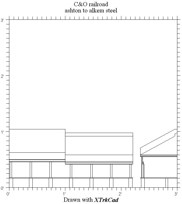
) ill buy his book,from what I've heard its a VERY in depth book.thanks all.--joshheres a detailed frontand undetailed as of yet side veiw of the furnace.it uh,is a little intricate....:mrgreen:.you can see the end veiws of the trusses,and little things like the mud gun and cold and hot blast pipes from the stoves.this whole complex is only 8in deep .it alot packed into that litle space.ill post a pic of the prototype BF that the cage came from.--josh
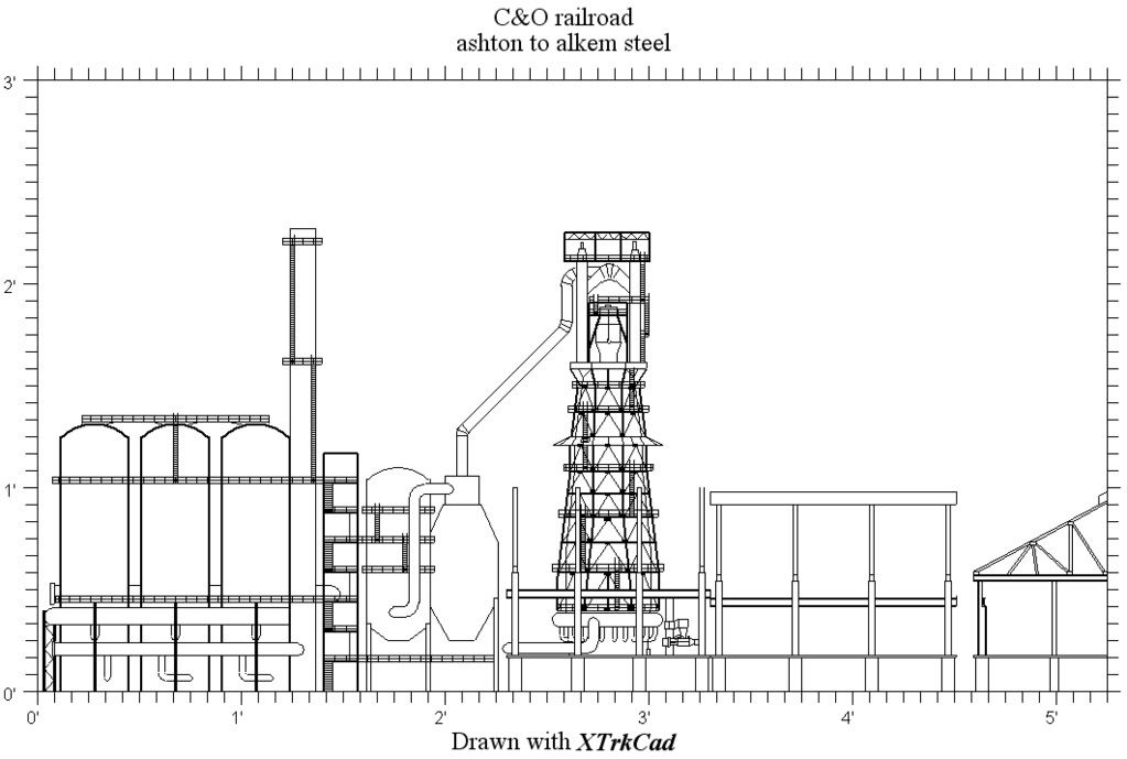
.it alot packed into that litle space.ill post a pic of the prototype BF that the cage came from.--josh
It's too bad that I wasn't aware of how much interest there is in the steel industry several years ago. I had a fairly complete set of the general blueprints for a blast furnace (not detail drawings, although those were available if I had needed them). A few years back, I finally cut up the last major component of my aborted blast furnace project: a double tracked skip bridge, with a pair of skip cars. At about 3' long, it had always been a nuisance to store. I used some of the steel rail from it on the crane runway shown in the photo that I posted earlier. If I ever get around to getting a scanner, I have a few photos of the model and also several of the prototype that I'll post. It would probably have been much easier to build in styrene than it was in mostly wood, with some styrene.
Wayne
Wayne
thanks wayne,it really does suck you had to throw away all your blueprints.i dont know how many peple that would've helped.but what are ya gonna do? stuff happens.although that BF you built sounds AWESOME :thumb:.although you do have the next best thing to blueprints,pictures.like they say,pictures are wortha thousand words :mrgreen:.--josh